Dual Servo Commander
SKU:The Dual Servo Commander allows you to rule the rotation of your servos. Each knob provides real-time servo control while six buttons store configurable travel positions. You can also use the buttons to select your preferred PWM range among four preset options during power-up!
Servo Connection
Two pairs of 2.54mm (0.1”) headers allow you to put up to four servos under the Dual Servo Commander’s control. Each knob can control up to two of those servos on a single channel.
If you need extra reach between the Dual Servo Commander and your servos, you can utilize its CAT-6 output to send all of its PWM output signals over a single CAT-6 cable of the length of your choice to the Servo Extension Receiving Board (SKU: 3116-4527-0001).
Voltage Input
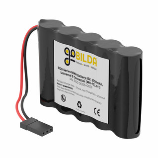
The Dual Servo Commander can be powered by a DC input voltage between 5 and 15V. The XT30 connector is the primary power input port; however, if you are using a battery with a connector similar to that of a servo (TJC8), you may plug it into the + and - pins at the top of the board. Make sure to use only one of the available power inputs at a time.
⚠️VOLTAGE WARNING:The voltage you power the Dual Servo Commander with will be passed on to the servos. DO NOT use a voltage that is higher than any of your servos is rated for. Sending a voltage higher than that for which a servo is rated will result in damage to the servo.
Servo Position Programming
Storing and recalling your servos' travel positions couldn’t be easier! It’s just like saving radio stations on a car’s stereo. When any of your servos are in a position you want to save, hold the button of your choice until its corresponding LED illumination is solid. (Both of the "A" and "B" channels have two buttons each, allowing for individual channel control. Use the pair of "AB" if you want to save and recall positions for both channels simultaneously.) When you press a button with a position saved to it, your servos will travel right back to the saved position!
If you'd like to use separate devices like sensors to move a servo to a saved position, or even save a position, you can externally trigger each button via JST PH connectors at the bottom of the Dual Servo Commander. To trigger a button, connect its JST PH connector's “s” pin to its “-” pin. Depending on if its duration is short or long, the connection will either activate servo travel to a position, or save a new position, respectively.
PWM Range Customization
The PWM range of the Dual Servo Commander applies to both of its channels simultaneously and can be customized according to your servos of choice. Each of the Dual Servo Commander’s 4 preset PWM ranges has been specially selected by the goBILDA® R&D team to provide you the best options for a variety of servos!
- 1050µs - 1950µs: The standard for 90° rotation.
- 850µs-2150µs: The typical max signal range for Hitec and Savox digital servos.
- 600µs-2400µs: Allows most analog servos to rotate 180°.
- 500µs-2500µs: Enables goBILDA® servos to achieve full travel!
It’s extremely easy to configure between preset ranges! No computer required. Just follow these steps:
- Power off Dual Servo Commander.
- Hold button of desired PWM range. (The four leftmost buttons correspond to the four ranges, from narrowest to widest.)
- Power on Dual Servo Commander while holding button.
- Release button when the corresponding LED illumination is solid.
Mounting
Thanks to its hex counterbores, the Dual Servo Commander is easy to mount to goBILDA® structural components via one-tool installation with M4 screws and locknuts. The mounting thru-holes are spaced 32mm x 80mm apart and are on-pattern to the underlying 8mm grid pattern of the goBILDA® build system.
Downloads
Specs
| Weight | 55g |
|---|---|
| Input Voltage Range (Limit) | 5 - 15VDC Do not supply a higher input voltage than that for which your servo is rated. |


